Intro
Our project, named TCRCT (Tilt Controlled RC Tank), is a radio controlled vehicle. But unlike traditional controllers with buttons and joy-sticks, TCRCT’s controller will guide the vehicle based on its tilt angle. So tilting the controller forward will accelerate the vehicle, and tilting it to the left or right will turn the vehicle.
Step 1
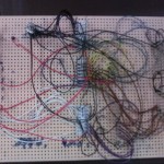
external memory
The first step involved interfacing with external memory using the External Bus Interface (EBI) ports. We use MULTI to interact with our board. Using MULTI we developed a program and downloaded it to the board. The program would store values in the RAM, and then read them back. We could verify that the RAM was error free if the values we wrote were the same values we read back.


Step 2
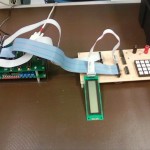
key pad
Step two interfaces with a key pad. However, unlike the RAM, we connected the key pad to the General Purpose Interface Bus (GPIO) ports. Again using MULTI we developed a program and downloaded it to the board. When a key was pressed, the value could be viewed in MULTI’s real time monitoring window.

Step 3
LCD from GPIO
Step three builds on step two. Instead of the key’s value being displayed in the terminal window, the value is sent to a LCD.


Step 4
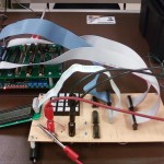
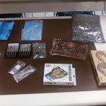
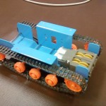
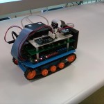
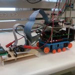
Tank Assembly
It felt just like Christmas today.
Step 5
LCD from EBI
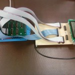
Unlike the above LCD installation, we must now use the EBI port to run the LCD. As you can see, this is more complicated as the timing of the LCD did not match the timing of the EBI.


Step 6
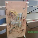
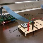
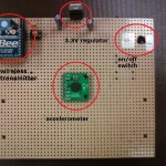
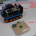
Controller
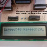
The controller will send wireless data to the tank. The tank will respond to the tilt angle of the controller.
Step 7
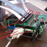
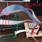
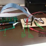
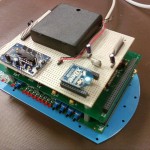
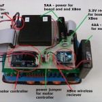
Control Board
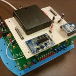
The control board bolts to the top of the microcontroller and interfaces the wireless receiver and motor controller. PWM signals from the microcontroller are sent to the motor controller, and wireless data receiver is sent to the microcontroller via the USART.


Step 8
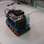
Testing – running from RAM
The RAM on the microcontroller is loaded with our program. We must connect to a computer via a serial cable when running from RAM.


Step 9
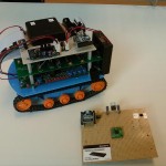
Testing – running from FLASH
The FLASH memory on the microcontroller is loaded with our program. We do not need to connect to a computer. The motor controller is used to display telemetry data from the tank when in FLASH as we are not connected to a computer, and therefore cannot use the computer’s monitor. The LCD was not included in the final tank packaging because of its weight and size. If we were able to replace the LCD’s wire wrapped board with a PCB, the unit would have been small enough to put on the tank.
Step 10
Tweaking
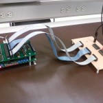
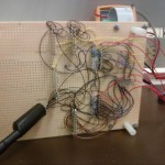
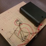
In the tweaking stage we spent time working on the tank’s reliability and fixing small bugs. One major change was the use of smaller ribbon cables. Not only do these cables look better, they produce less electrical noise (which was interfering with the board and causing random resets). We also experimented with longer risers (again to reduce electrical noise), and removing screws with hopes of reducing weight.


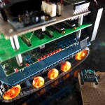
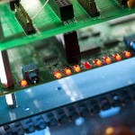
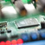
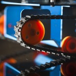
Final Step !
HD Image Gallery
Click images for bigger views
Feel free to make any of these your desktop background !