First Run Heat Issues:
The server was initially intended to run without any fans. The CPU is/was low power and comes with a fan-less heat-sink, and the HDD’s are pretty much out in the open. Perfect, I thought, lets get this show on the road. Upon first power up it was apparent this was going to be an issue. The CPU slowly started to rise up to its 80C alarm limit, and the HDD’s quickly shot up to 47C. Ideally, the CPU should be in the mid 30’s and the HDD’s should be under 40C.
To fix the issue, the main fan was connected to the server’s motherboard. Straightforward right? nope… The motherboard is only setup to control 4-pin PWN fans, and thus blasts the fans with a constant +12V. The 3-pin fan shot right up to 3000 RPM. To lower the speed and noise, I installed a resistor inline with the fan’s power lead. This drooped the voltage to the fan to where it now sits at a nice quiet 1000 RPM. The CPU now runs around the 35C mark.
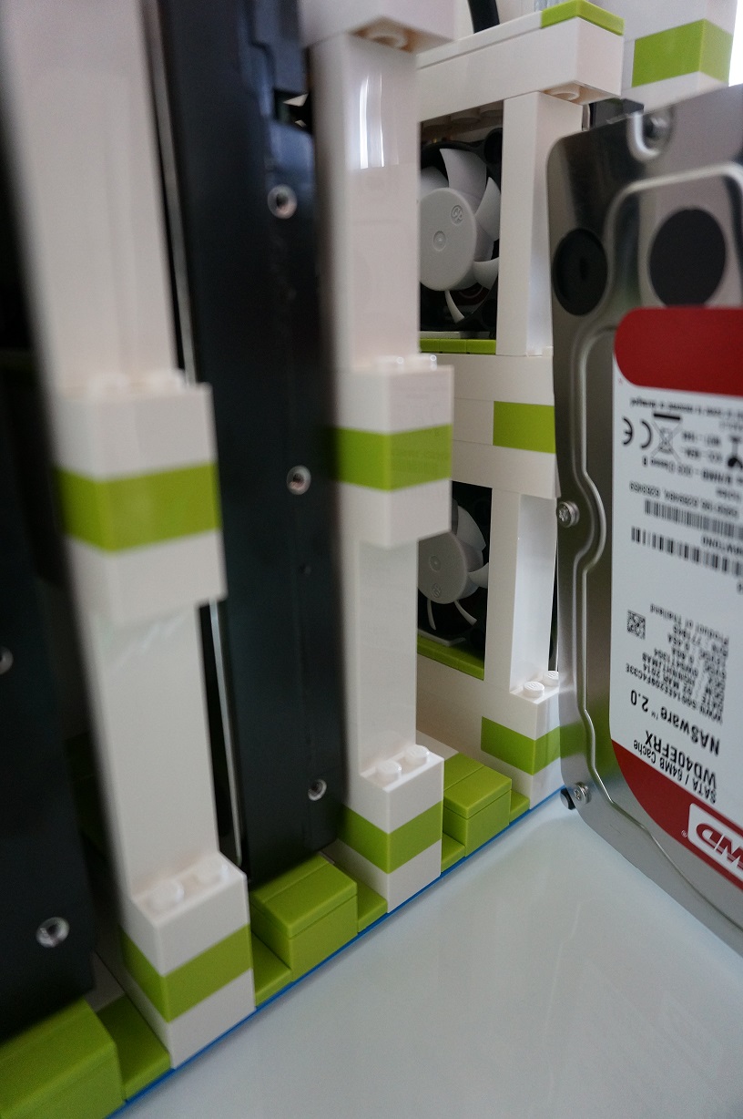
The HDD’s presented more of a challenge as the case was designed to be fan-less. I had some 40mm fan lying around, and again luckily for me, they were a perfect fit into the existing ventilation gaps. The fans were all connected to the server’s motherboard. Straightforward right? nope… The motherboard is only setup to control 4-pin PWN fans, and thus blasts the fans with a constant +12V. The 3-pin 3-pin fan shot right up to 4000 RPM. To lower the speed and noise, I connected the fans to the +5V rail off the power supply. They now run at a nice quiet 1000 RPM. The HDD’s now run around the 37C mark.
Google has published a really nice white paper on HDD failure analysis. The paper focuses on consumer grade HDD’s and operating conditions effecting their longevity. http://research.google.com/pubs/pub32774.html. This is where I’m getting my temperature target of under 40C from.
— Update —
More Heat Issues:
Although elegant and simple, the above solution did not work as planned. In trying to the make most of that situation, I ended up installing a total of seven 40mm fans into the gaps shown above. And while they did lower the drive’s temperatures, they just weren’t able to keep them below 40C. They would idle at 37C or so, but on a warm day or under load they had no trouble getting up to 40C / 41C.
Enter solution #2. The 40mm fans were originally connected to the power supply’s 5V rail in hopes that 5V would spin the fans slowly and quietly. And it did just that. They were very quiet, but ultimately ineffective. This solution was to connect them to the 12V rail in hopes that a faster fan speed would provide extra cooling. All this really did was increase the noise they produced. No noticeable change in temperature. If I had to guess why, it would be the fans’ location. They were just circulating hot air.
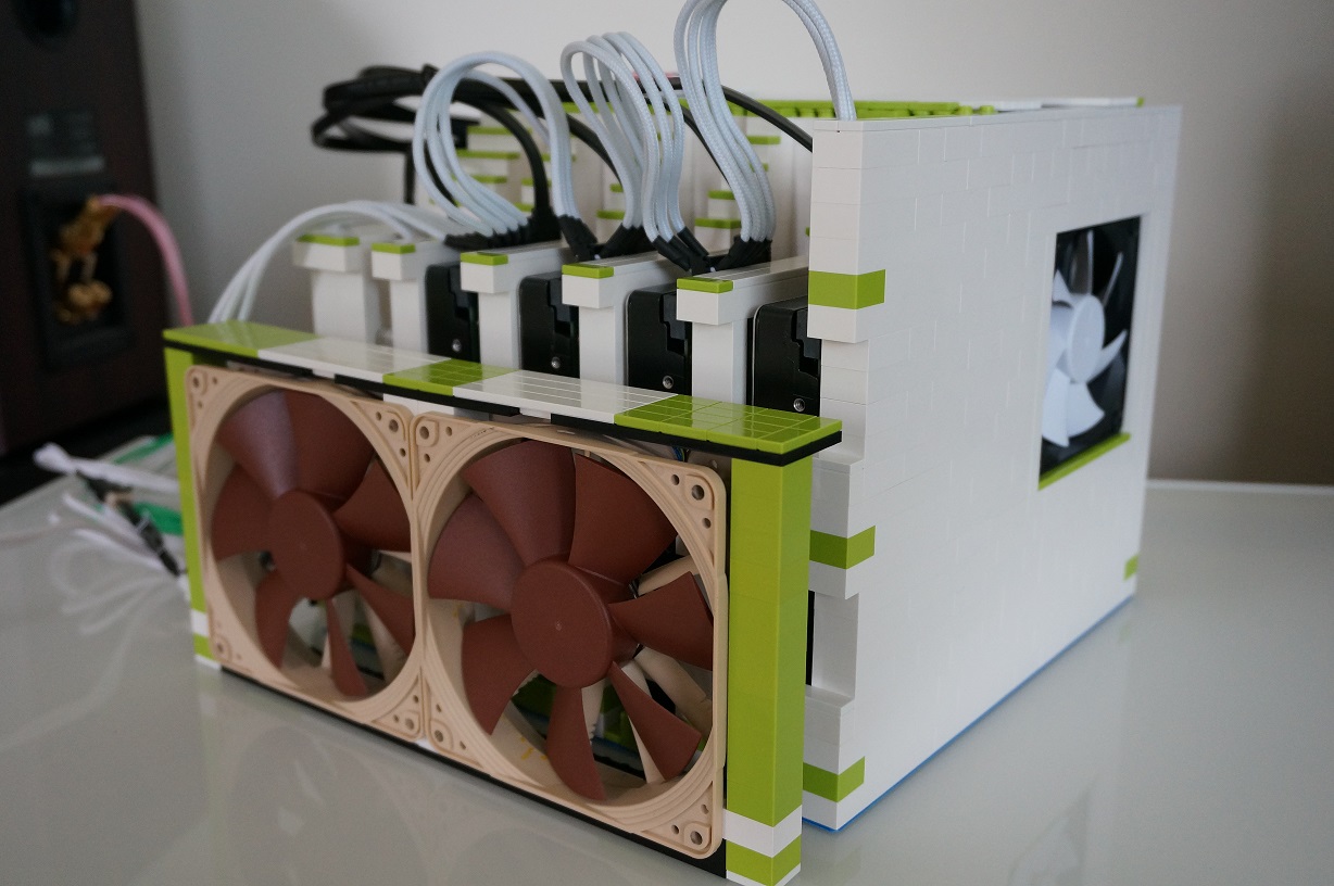
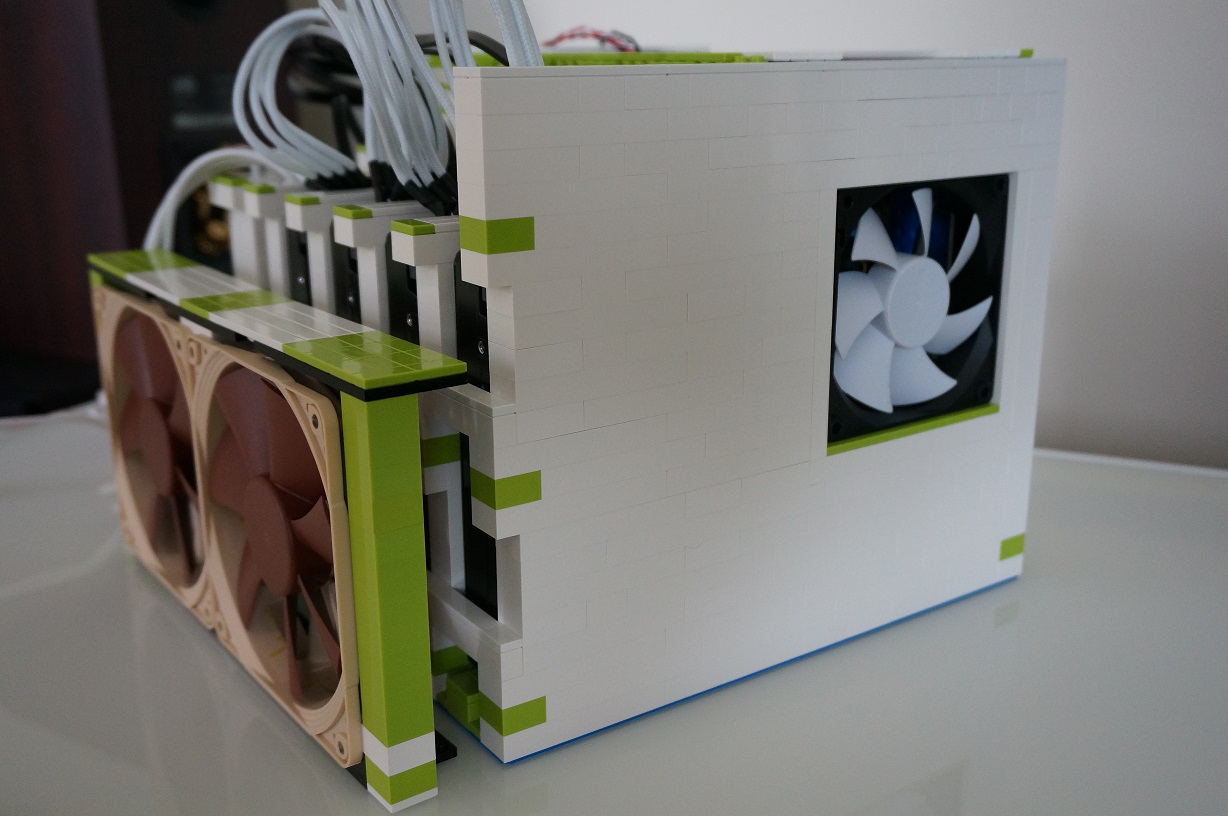
Enter solution #3. The 40mm fans were removed altogether. Replaced by two 120mm fans sitting external to the enclosure. This would allow them to blow cool air at the drives, and move more air than seven 40mm fans ever could.
The 40mm fans are spec’d to move about 4cfm air. Multiply that by seven and the total volume of air they were able to move was 28cfm. Now looking at the 120mm fans, they are spec’d to move about 74cfm of air each, and I have two of them, producing a total of 148cfm or about 5x the volume. I know, I know, ugly Noctua brown. But they’re what I had lying around…
Case in point:
Without any fans the drives would idle at 47C.
With four 40mm fans @ 5V the drives would idle at 38C.
With seven 40mm fans @ 5V & 12V, the drives would idle at 37C.
With two 120mm fans, the drives now idle at a cool 28C.